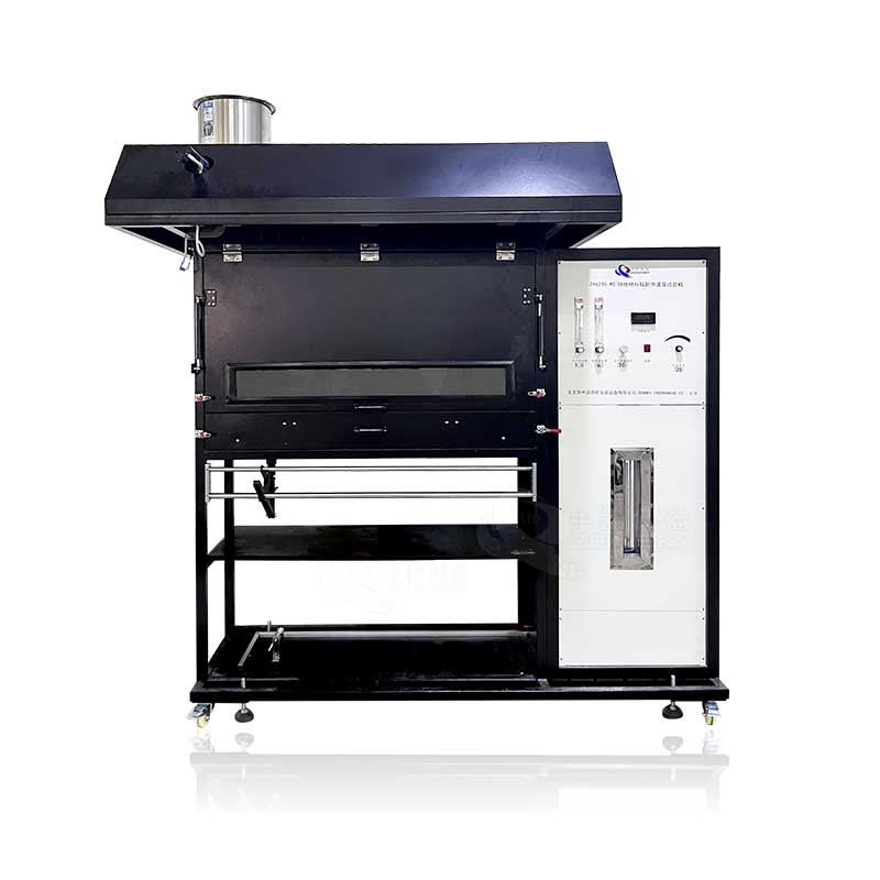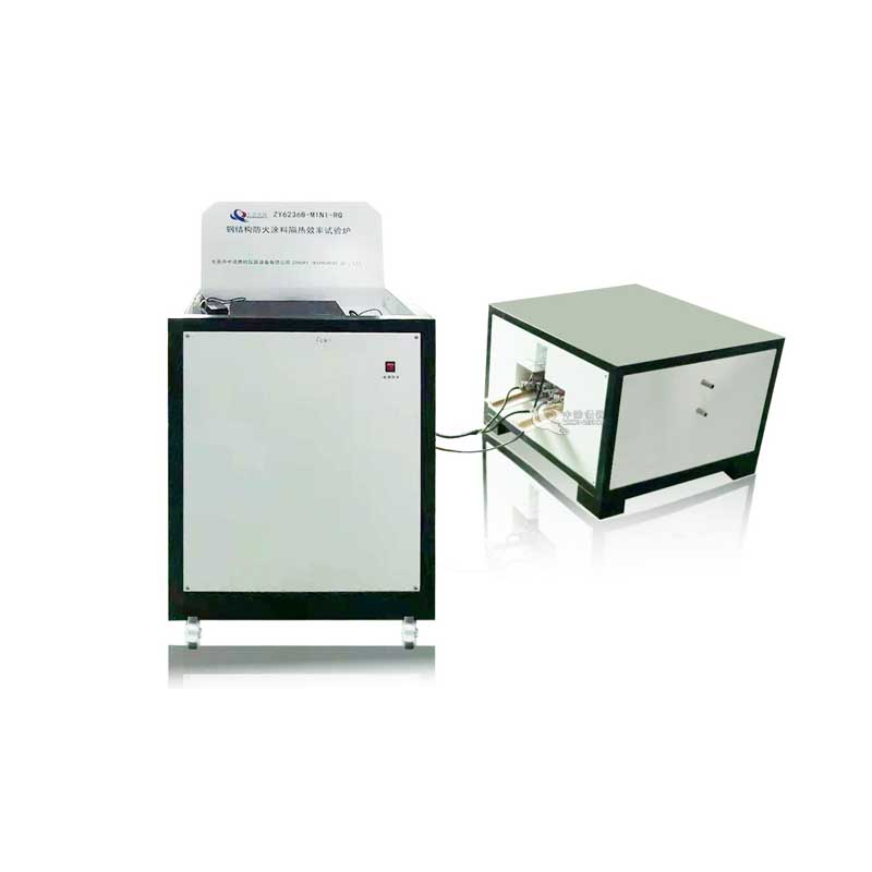
The Fire Resistance Test Furnace suitable for the test of thermal insulation performance deviation and thermal insulation performance attenuation of steel structure fire retardant coatings.
1. Scope of application:
It is suitable for the test of thermal insulation performance deviation and thermal insulation performance attenuation of steel structure fire retardant coatings.
Heating curve conditions:
The temperature and pressure in the test furnace comply with the relevant regulations in GB/T9978.1-2008 Sections 6.1 and 6.2;
Hydrocarbon (HC) fire heating conditions, the temperature in the test furnace conforms to the relevant regulations in Article 5.1.2 of GA/T714-2007, and the pressure in the furnace is maintained at positive pressure (optional heating conditions).
2. Compliant standards:
2.1 Comply with the test requirements of Chapter 5 and Chapter 6 of GB/T9978.1-2008 "Fire-Resistance Tests—Elements of Building Construction—Part 1: General Requirements".
2.2 Comply with the test standard of Appendix A of GB/T14907-2018 "Fire Resistive Coating for Steel Structure";
2.3 Comply with the standard requirements of GA/T714-2007 "Rapid rise fire test methods of fire protection materials for structure elements" (optional standard).
3. Main features:
3.1 The sixteen-bit high-precision acquisition card is used to collect various data such as temperature, pressure, flow, etc., and the real information of real-time reproduction of combustion is generated by microcomputer analysis, processing and control, and is directly obtained by microcomputer analysis and judgment. As a result, the whole machine adopts high-quality components to ensure high-quality, high-speed operation of the system, which is advanced.
3.2 It adopts 16-bit high-precision acquisition card + multi-channel module + microcomputer, and implements PID automatic control mode, with excellent stability, repeatability and reproducibility.
3.3 It adopts WINDOWS XP operation interface and LabView, the special development software for global precision equipment. The interface style is fresh, beautiful and simple. During the test, the measurement results are displayed in real time and the perfect curve is dynamically drawn. The data can be permanently saved, recalled and printed out, and the report can be printed directly. It has the characteristics of high intelligence, guided menu operation, simple and intuitive, and makes the test results more accurate.
3.4 Furnace Construction: Furnace construction should adopt American GOVMARK technology. Five-layer structure, when the inner layer is 1300°C, the temperature of the outer layer is normal temperature; the service life is long, and the insulation material of the inner layer is easy to replace.
4. Project installation and overall planning:
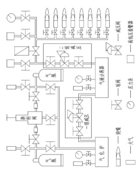
4.1 The test furnace uses 50kg filling combined liquefied petroleum gas as fuel, and adopts automatic control circuit. When the pressure is lower than the set value during the test, the liquid phase switching valve will automatically switch to another group, which can prevent the sudden consumption of gas during the test. exhausted, thereby interrupting the test.
4.2 In order to fully burn the gas after gasification, an air-fuel proportional valve is added to automatically adjust the ratio of air and gas to achieve the best combustion calorific value.
4.3 Burner: with automatic alarm device for ignition failure and flame extinguishing.
4.4 Burners: 2 sets are heated for fiber fires (4 sets are heated for hydrocarbons).
4.5 Fuel consumption: The fuel consumption can meet the test heating speed control, and contains a variety of working modes to adapt to the corresponding economical gas consumption in various working modes.
5. Main technical parameters:
5.1 Instrument composition: fire resistance test vertical furnace, combustion control part, gas part, pressure release and pressure measurement system, flue gas emission system, computer control system, temperature measurement system (furnace temperature data acquisition system, test component temperature acquisition system) and special test software.
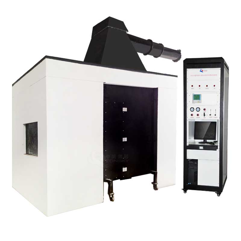
5.2 Test furnace: It is a horizontal test furnace, and the size of the furnace is 1200mm (length) x 1050mm (width) x 450mm (depth).
5.3 Number of samples: It can meet the test of three samples at the same time.
5.4 Furnace body structure: Five-layer structure is adopted. When the inner temperature is 1300°, the outer layer temperature is normal temperature. From outside to inside, they are: the first layer is steel structure frame; the second layer is made of red bricks; the third layer is refractory high temperature asbestos; the fourth layer is refractory brick; the fifth layer is mullite refractory high temperature cotton. The refractory temperature reaches 1600°C. The furnace body does not exceed 45 degrees.
5.5 High pressure burner:
5.5.1 Use 2 sets of 150kw power high pressure burners (4 sets of hydrocarbon heating), the burners have air-fuel ratio control, and are equipped with corresponding gas control valves and air control valves to achieve the best combustion effect. In order to ensure safety, the burner selection and components use well-known domestic brands;
5.5.2 Burner: with automatic alarm device for non-ignition and flame extinguishing;
5.5.3 There are 2 high-speed burners embedded on both sides of the furnace wall, 1 on each side (4 in total for hydrocarbon heating, 2 on each side). It provides the heat needed to raise the temperature in the furnace.
5.5.4 Ignition control mode: There are two control modes of computer program automatic ignition and high voltage electronic ignition. There is an automatic ignition method in the program. The number of torches used in the furnace meets the requirements of the standard time-temperature curve and ensures the uniformity of the temperature at each point in the furnace.
5.6 Gas pipeline and air pipeline: composed of butterfly valve, air-fuel proportional valve, secondary pressure reducing valve, manual butterfly valve, ignition controller, high and low pressure switch, gas overpressure relief valve, gas gas-liquid separator, primary pressure reducing valve Valve, liquid phase switching valve, gas pressure gauge, low pressure gauge, ball valve, gas leakage alarm, stainless steel hose, gas high pressure hose, etc.
5.7 Temperature measurement system:
5.7.1 Thermocouple in the furnace: The furnace adopts K-type nickel-chromium-nickel-silicon thermocouple with a wire diameter of 0.5mm in accordance with GB/T 16839.1, the outer cover is a heat-resistant ceramic sleeve, and the middle is filled with heat-resistant materials. The length of the end protruding from the casing is not less than 25MM, and the temperature resistance is more than 1300 degrees. It has 4 thermocouples in total;
5.7.2 The temperature measurement of the backfire surface: a thermocouple with a diameter of 0.5MM is used, which is welded on a circular copper sheet with a thickness of 0.2MM and a diameter of 12MM. , should be covered with asbestos liner with a length and width of 30MM and a thickness of 2.0MM.
5.7.3 The temperature rise curve in the fiber fire furnace: the maximum combustion duration of each time is 360min, and the maximum temperature is 1300℃. The temperature rise curve should be carried out according to the table below.
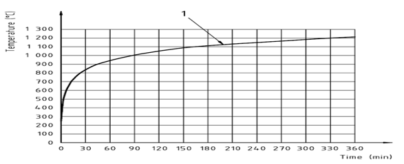
Furnace temperature uniformity: the difference between the thermocouple acquisition temperature and the standard curve < 100 ℃
It satisfies the requirements of the rising control deviation, namely:
de≤15% for 5< t ≤10
de=15-0.5(t-10) % for 10< t ≤30
de=5-0.083(t-30)% for 30< t ≤60
de=2.5% for t > 60
5.7.4 Hydrocarbon fire heating curve: in line with Section 5.1.2 of GA/T714-2007;
5.8 Accuracy of measuring instruments:
5.8.1 Measuring temperature: inside the furnace: ±15℃;
5.8.2 Back fire side: ±2.5℃;
5.8.3 Furnace pressure: ±3 Pa;
5.8.4 Time: ±1s/h;
5.9 Pressure measurement system:
5.9.1 The pressure measurement in the furnace: the measurement range is 0-100Pa; the differential pressure gauge imported from the United States is used, which is a T-shaped measuring probe, and the measurement accuracy is ±0.5pa. It has the function of overpressure protection, and the pressure in the furnace is higher than 100Pa to execute the program overpressure protection, stop the gas supply, and terminate the test; it complies with the GB/T9978.1-2008 standard.
5.9.2 The pressure in the furnace is recorded every 1 min, and the accuracy of the recording equipment is 1s. Data collection is 3 times/second. Furnace pressure control and data acquisition, the furnace pressure can ensure real-time control according to the requirements of each standard of "Chapter II Compliance with Standards" and the smoke exhaust system to form a control loop;
5.9.3 T-shaped measuring probe: USU310S high-temperature-resistant stainless steel pipe is used to pass through the furnace wall from the furnace to the outside of the furnace, and the pressure inside and outside the furnace keep the same level.
5.9.4 Pressure transmitter: high-precision pressure sensor. It is 15pa±5pa within 5 minutes of the test, and 17pa±3pa after 10 minutes.
5.10 Pressure relief system:
5.10.1 A smoke exhaust hole is installed on the furnace wall on the back side of the furnace body, which is connected to the exhaust pipe to discharge the flue gas in the furnace body to control the pressure. Control the pressure in the furnace. The air supply and exhaust in the furnace are controlled by a 1.5kw powerful fan and a frequency converter, and the air volume is automatically controlled by a computer program to meet the requirements of combustion, pressure and smoke exhaust.
5.10.2 Pressure release pipeline: The part in the furnace is made of high temperature-resistant diameter 300mm, USU310S stainless steel tube, which can withstand high temperature of 1300 ℃, and has a manual valve on the upper part for air cooling. A welded pipe with a wall thickness of 5mm is used outside the furnace.
5.10.3 Pressure release power: AC380, 1.5kw high-pressure fan with high temperature resistance.
5.10.4 Cooling method: adopt air-cooling cooling method.
5.10.5 Furnace pressure control and data acquisition, the furnace pressure can ensure real-time control of the control loop formed with the smoke exhaust system according to the requirements of the above standards;
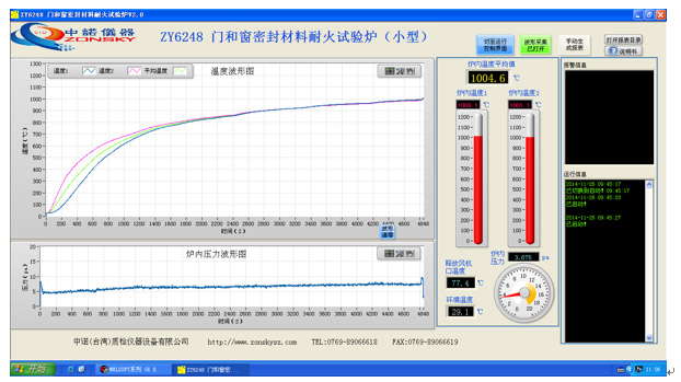
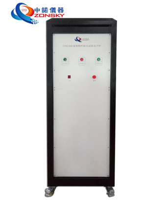
5.11 Computer control system and data acquisition: see Image 5
5.11.1 Using computer + module + PLC + PID and other control systems, the interface includes: main control interface, furnace temperature curve interface, pressure display, specimen temperature interface, with historical data storage, query and other functions, and can be converted to EXCEL file storage .
5.11.2 The test records (3 seconds/time) are stored by number and can be queried at any time; the printing effect of the test report can be viewed in real time, and it can be completed by simply clicking the buttons such as start, calculation and save, which is easy to use.
5.11.3 At the same time, the data retrieval function is added, which can load the previous experimental data for recalculation and form a report.
5.11.4 Control system hardware: One set of Mitsubishi PLC from Japan; 64 channels of 16-bit high-precision acquisition card; 60 temperature transmission modules.
5.12 Test furnace installation conditions:
5.12.1 The furnace covers an area: 3 meters long * 3 meters wide * 3.5 meters;
5.12.2 The ground is flat, the thickness of the foundation concrete is more than 100mm, the surrounding is well ventilated, and it does not contain flammable, explosive, corrosive gas and dust.
5.12.3 Appropriate maintenance space is reserved around the equipment.
5.12.4 Temperature: 5℃~40℃.
5.12.5 Air pressure: 86~106kpa.
5.12.6 AC220V/50HZ.
5.12.7 The allowable voltage fluctuation range: 220V±10%.
5.12.8 Allowable frequency fluctuation range: 50Hz±1%.
5.12.9 The user is required to configure an air and power switch with corresponding capacity for the equipment at the installation site, and this switch must be independent and dedicated to the equipment.
5.12.10 When the equipment is not working, the temperature of the environment should be kept within +0~45℃.
5.12.11 The whole machine is all grounded.
 WhatsApp:
 Mobile Phone:
 Contact Now