(SBI) Test Apparatus Complies with EN 13823:2002 Reaction to fire tests for building products—Building products excluding floorings exposed to the thermal attack by a single burning item.
1. Scope of application:
1.1 Test method suitable for determining the fire response properties of building materials or products (excluding floor coverings and products specified in EC Decision 2000/147/EC) in the single burning test (SBI).
2. Comply with standards:
2.1 Comply with EN 13823:2002 Reaction of building products to fire. Test method for individual combustion of building products excluding flooring materials.
2.2 Comply with EN 13823:2010 Fire reaction of building products. Single combustion test method for building products excluding flooring materials.
3. Main features:
3.1 Maintenance is convenient and fast. The replacement of spare parts in the later period is at least 50%~70% lower than that of FTT, so there will be no trouble in maintenance. The instrument has a long service life and low operating costs.
3.2 Use integrated control cabinet.
3.3 Using heptane calibration, the heat release (THR) value per KG is 4456MJ/KG±222.8MJ/KG; the flow rate distribution factor Kt,v is very stable after repeated measurements. The instrument has good accuracy, high precision, stability and reliability.
3.4 Equip with corresponding auxiliary equipment and consumables to ensure the normal operation of the instrument.
3.5 Provide product printing color samples and detailed equipment instructions
4. Main technical parameters:
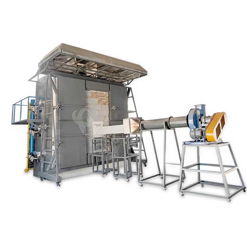
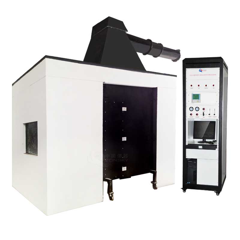
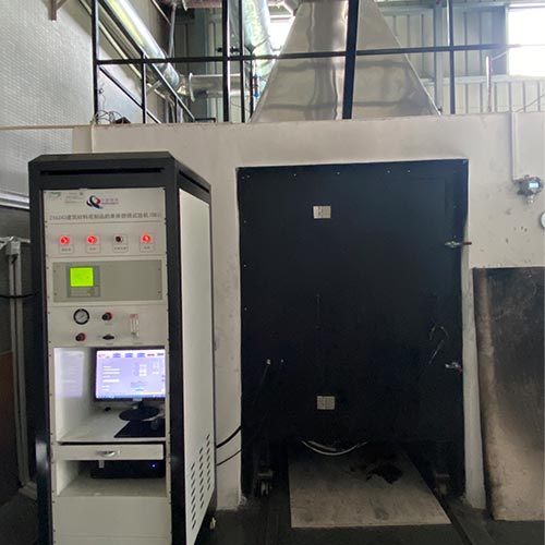
4.1 Instrument composition: including combustion chamber, test equipment (trolley, fixed frame, burner, gas collecting hood, collector and duct), J-type smoke exhaust pipe, flue gas collection system, comprehensive measurement system device, data collection and analysis Device, gas supply control device (the overall equipment placement space is 6.0m high × 7.0m long × 6.0m wide including the control room space, and the placement space can also be reasonably planned according to the buyer's site).
4.2 One combustion chamber:
4.2.1 Dimensions of the combustion chamber: length (3.0±0.2) m × width (3.0±0.2) m × height (2.4±0.1) m. The combustion chamber is built with brick walls.
4.2.2 There is a gas collecting hood and smoke exhaust duct connected to the sampling pipe at the top of the room. During the test, the heat released by the combustion of the sample and the combustion products must be discharged from the smoke exhaust pipe.
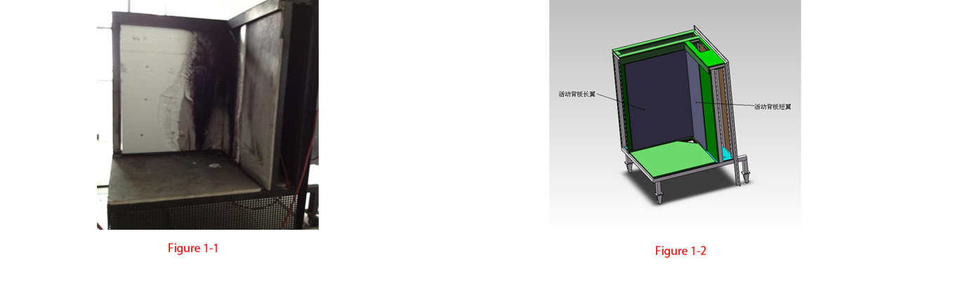
4.2.3 An opening is provided on one side of the combustion chamber to facilitate moving the trolley into the combustion chamber from the adjacent laboratory. The dimensions of the opening (frame) are: width 1470mm x height 2450mm. There is natural air in and out under the trolley. space; there are observation windows on the two walls facing each of the long wings and short wings of the vertical specimen plate.
4.2.4 There is a closable door on one side of the combustion chamber to facilitate cleaning of test residues in the room after the test.
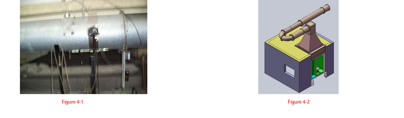
4.2.5 After the trolley is in place in the combustion chamber, the distance between the test surface of the long wing in contact with the U-shaped slot and the quality inspection surface of the combustion chamber wall is (2.1±0.1) m. This distance is between the long wing and the surface facing it. The vertical distance from the wall, the opening area of the combustion chamber (excluding the air inlet at the bottom of the trolley and the smoke exhaust opening of the air collection hood) is 0.05m2, as shown in Figure 4.
4.3 Fuel: commercial propane gas, purity ≧95%.
4.4 Test equipment:
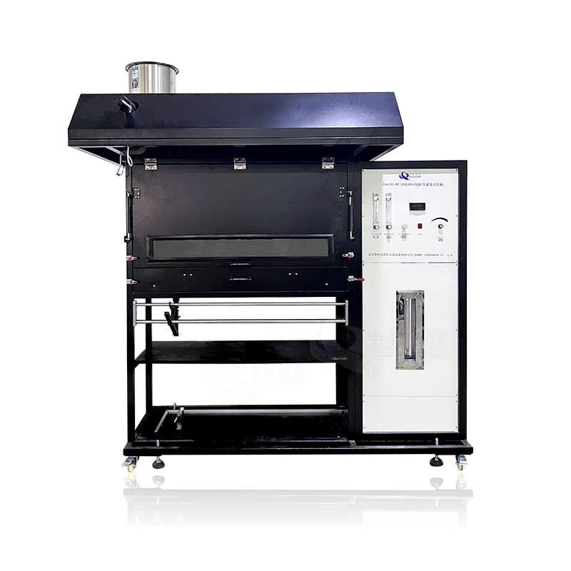
4.4.1 Sample loading trolley: Two mutually perpendicular sample specimens are installed on it (the long wing is a 1.5M wing and the short wing is a 1.0M sample). There is a sand box burner at the bottom of the vertical angle. The cart is positioned so that the back of the cart just closes the opening on the combustion chamber wall. In order to distribute the air flow evenly along the combustion chamber floor, a porous plate is installed at the air inlet under the bottom of the cart (its opening area accounts for the total 40% to 60% of the area, hole diameter is 8mm to 12 mm). As shown in Figure 1
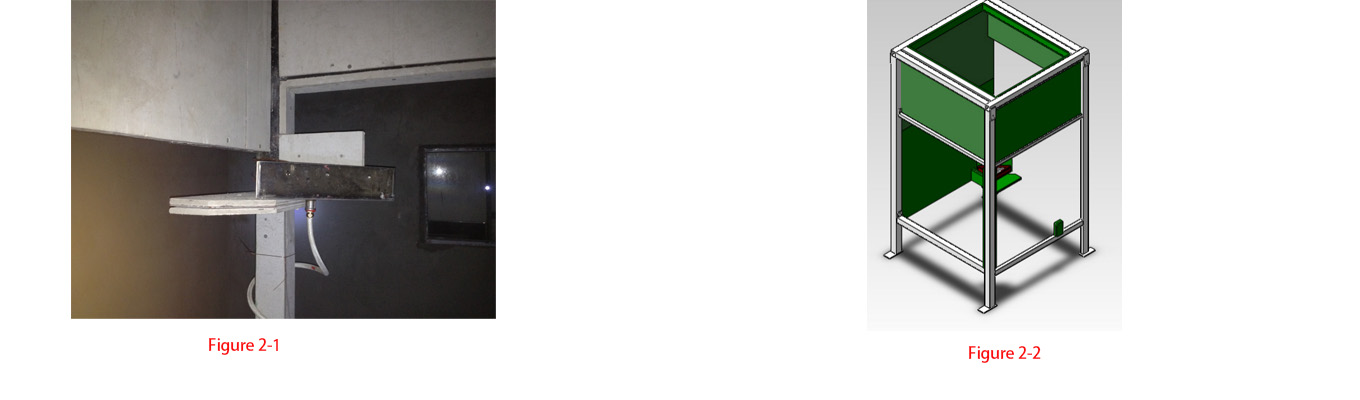
4.4.2 Fixed frame: It is made of square steel, strip steel and asbestos board. The trolley is pushed into it for testing and supports the gas collecting hood. The auxiliary burner is fixed on the frame. As shown in Figure 2
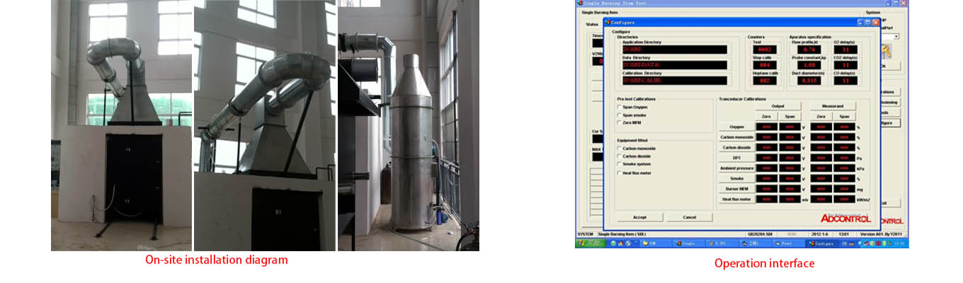
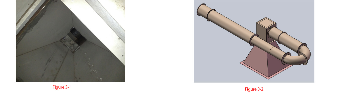
4.4.3 Gas collecting hood: Located on the top of the frame, it has a cone shape with a bottom length x width of 1479mm. The inner material is USU304 stainless steel and the outer material is galvanized sheet. It is used to collect the gas generated by combustion; see Figure 3
4.4.4 Collector: located at the top of the gas collecting hood, with a damper plate and a horizontal outlet connected to the exhaust duct. The outer size is 580mmx580mm square, the inner material is USU304 stainless steel, the outer material is made of galvanized sheet, and the middle is insulation cotton.
4.4.5 J-type smoke exhaust pipe: a double-layer insulated round pipe with an inner diameter of 315mm±5mm. The middle is insulated with 50mm thick high-temperature resistant mineral wool. The inner material is USU304 stainless steel and the outer material is made of galvanized sheet. Equipped with the following components along the air flow direction:
① The joint connected to the collector is connected by a flange;
② A pipe with a length of 500mm, with 3 built-in thermocouples (thermocouples for temperature measurement), and the installation position of the thermocouples should be at least 400mm from the collector;
③ Pipe length 1000mm;
④ Two 90° elbows (the radius of curvature of the shaft is 400mm);
⑤ A pipe with a length of 1625mm, with a blade deflector and an orifice plate. The deflector is 50mm away from the end of the elbow, and the length is 630mm. Immediately after the deflector is a section with a thickness of (2.0±0.5)mm. The orifice plate has an inner opening diameter of 265mm and an outer opening diameter of 314mm;
⑥ A pipeline with a length of 2155mm, equipped with a pressure probe, a micro-pressure measuring device (2 units), four thermocouples, a gas sampling probe (2 units) and a white light extinction system. This part is called the "comprehensive measurement area"; see the figure 8
⑦ Pipe length 500mm;
⑧ Connector to the smoke exhaust system. See Figure 4
4.4.6 There are two identical sandbox burners, one of which is located on the bottom plate of the trolley (as the main burner), and the other is fixed on the frame column (as the auxiliary burner). The propane gas passes through the sandbox burner and Produces a heat output of 30.7±2.0kW with the following specifications:
① The shape of the sand box burner: an isosceles right triangle with a waist length of 250mm (top view) and a height of 80mm. The bottom is open at the top and the rest is closed except for a pipe socket with a diameter of 12.5mm at the center of gravity. A right-angled triangular porous plate should be installed at a height of 10mm from the bottom of the burner. Wire screens with a maximum mesh size not exceeding 2mm should be installed at a height of 12mm and 60mm from the bottom. All dimensional deviations should not exceed ±2mm.
② Material: The box body is made of 1.5mm thick stainless steel, continuously distributed from bottom to top: a gap layer with a height of 10mm; a pebble layer with a size of (4-8)mm and a filling height of 60mm; a layer of pebbles with a size of (2- 4)mm, sand and gravel layer with a filling height of 80mm. The pebble and sand layers are stabilized with wire mesh to prevent pebbles from entering the gas pipeline. The pebbles and gravel used are round and free of gravel.
③ Position of the main burner: The main burner is installed on the bottom of the trolley and is close to the U-shaped slot at the bottom of the sample. The top edge of the main burner is consistent with the top edge of the U-shaped slot, and the difference does not exceed ±2mm.
④ Position of the auxiliary burner: The auxiliary burner is fixed on the frame column at an angle opposite to the sample, and the top of the burner is (1450±5)mm higher than the combustion chamber floor (the vertical distance from the gas collecting hood is 1000mm) , its hypotenuse is parallel to the hypotenuse of the main burner and is closest to the hypotenuse.
⑤ The main burner is close to the U-shaped slot at both the long and short wings of the specimen. In the U-shaped slots in both directions, there is a baffle, the top surface of which is the same height as the top surface of the U-shaped slot, and is 0.3m away from the angular edge of the two wings of the installed specimen (in the burner area border).
⑥ If previous tests of similar products ended prematurely due to material dripping onto the sand bed, the main burner should be protected by an oblique triangular grille, and the opening area of the grille should account for at least 90% of the total area. One side of the grille is placed on the beveled edge of the main burner. The angle between the oblique triangular grid and the horizontal plane is (45±5)°. This angle can be measured by drawing a horizontal straight line from the midpoint of the hypotenuse of the main burner to the angle between the sample.
4.4.7 Rectangular shielding plate: width (370±5)mm, height (550±5)mm, made of calcium silicate board (its specifications are the same as the backing plate), used to protect the sample from auxiliary Influence of burner flame radiation heat. The rectangular shielding plate should be fixed on the hypotenuse of the bottom surface of the auxiliary burner. The center of its bottom edge is located at the center of the hypotenuse of the bottom surface of the burner and covers the entire length of the hypotenuse. Both ends protrude (8±3)mm, and its top edge is (470±5)mm higher than the top of the auxiliary burner.
4.4.8 Mass flow controller: Measuring range: 0~2.5g/s, of which in the measuring range (0.6~2.5) g/s; accuracy 1%; digital display, with 4~20mA output, directly controlled by computer through acquisition card , fast response speed and high control accuracy.
4.4.9 Gas supply switch: The main and auxiliary burners switch to ignite the auxiliary burner at 120±5S and adjust the flow rate of the propane burner to (647±10) mg/s. The propane gas is switched from the auxiliary burner at 300±5S. to the main burner; used to supply propane gas to one of the burners. The switch places propane gas to be supplied to both burners at the same time, except for the time period when the burner is switched (at the moment of switching, the gas output of the auxiliary burner is The output of the main burner is decreasing while the output of the main burner is increasing), the switching response time of the burner does not exceed 12s, and the switch and the above-mentioned main valves can be operated outside the combustion chamber.
4.4.10 Back plate: used to support the two wings of the specimen in the trolley. The material of the backboard is calcium silicate board, its density is (800±150)kg/m3, thickness is (12±3)mm, and its dimensions are:
① Short wing back plate: (>570+sample thickness)mm×(1500×5)mm;
② Long wing back panel: (1000+gap width±5)mm×(1500±5)mm.
③ The short wing back plate is wider than the specimen, and the excess width can only extend from one side. For specimens mounted with a gap, increase the width of the long wing back plate by an amount equal to the size of the gap.
4.4.11 Movable panels: To allow increased airflow behind the wings of the specimen, they should be replaced with panels half their size to cover the upper half of the gap.
4.4.12 Ignition source: 31KW propane right-angle sandbox burner (side length 250MM and height 80MM) placed in a vertical corner on a trolley.
4.4.13 Using adjustable clamps, it is very convenient to load and unload samples.
4.5 Flue gas sampling system:
4.5.1 Flue gas sampling system: It consists of sampling tube, soot filter, cold trap, drying column, pump and waste liquid regulator, which can ensure the effective collection of flue gas samples and absorption of tail gas.
4.5.2 A comprehensive sampling area is provided in the smoke exhaust duct for placing sensors and sampling pipes.
4.5.3 Smoke exhaust flow rate range: 0.50 cubic meters/S ~ 0.65 cubic meters/S (standard temperature is 298K) to continuously exhaust smoke; use a computer to control the fan through frequency conversion and automatically adjust the wind speed;
4.5.4 The smoke exhaust duct is equipped with two side pipes (circular pipes with an inner diameter of 45mm), which are horizontal and perpendicular to the longitudinal axis of the smoke exhaust duct and the height of their axis is equal to the height of the longitudinal axis of the smoke exhaust duct.
4.5.5 Ambient temperature measurement in the test room: K-type armored thermocouple with a diameter of 1mm, temperature measurement accuracy of 0.5°C, environmental pressure test: ±200Pa.
4.5.6 Diaphragm pump: flow rate: 60L/min, vacuum degree: 700㎜Hg, pressure: 2.5 bar.
4.5.7 Smoke filter: The filter head is composed of solid PTFE, and the inside is 0.5um PTFE filter material.
4.5.8 CO2 filter: Built-in CO2 filter material, the filter head is made of solid PTFE and is highly anti-corrosion.
4.5.9 Moisture filter: The filter head is composed of solid PTFE, and the liquid at the bottom can be discharged through a peristaltic pump.
4.5.10 Cold trap: It is a compressor condenser with a cooling capacity of 320KJ\h, dew point stability of 0.1 degrees, dew point static change of 0.1K, and protection level IP20.
4.5.11 Rotameter: measuring range is 0-5L\min.
4.6 Comprehensive measuring device:
If you want to know more about our products please contact us!
 WhatsApp:
 Mobile Phone:
 Contact Now