Product Details
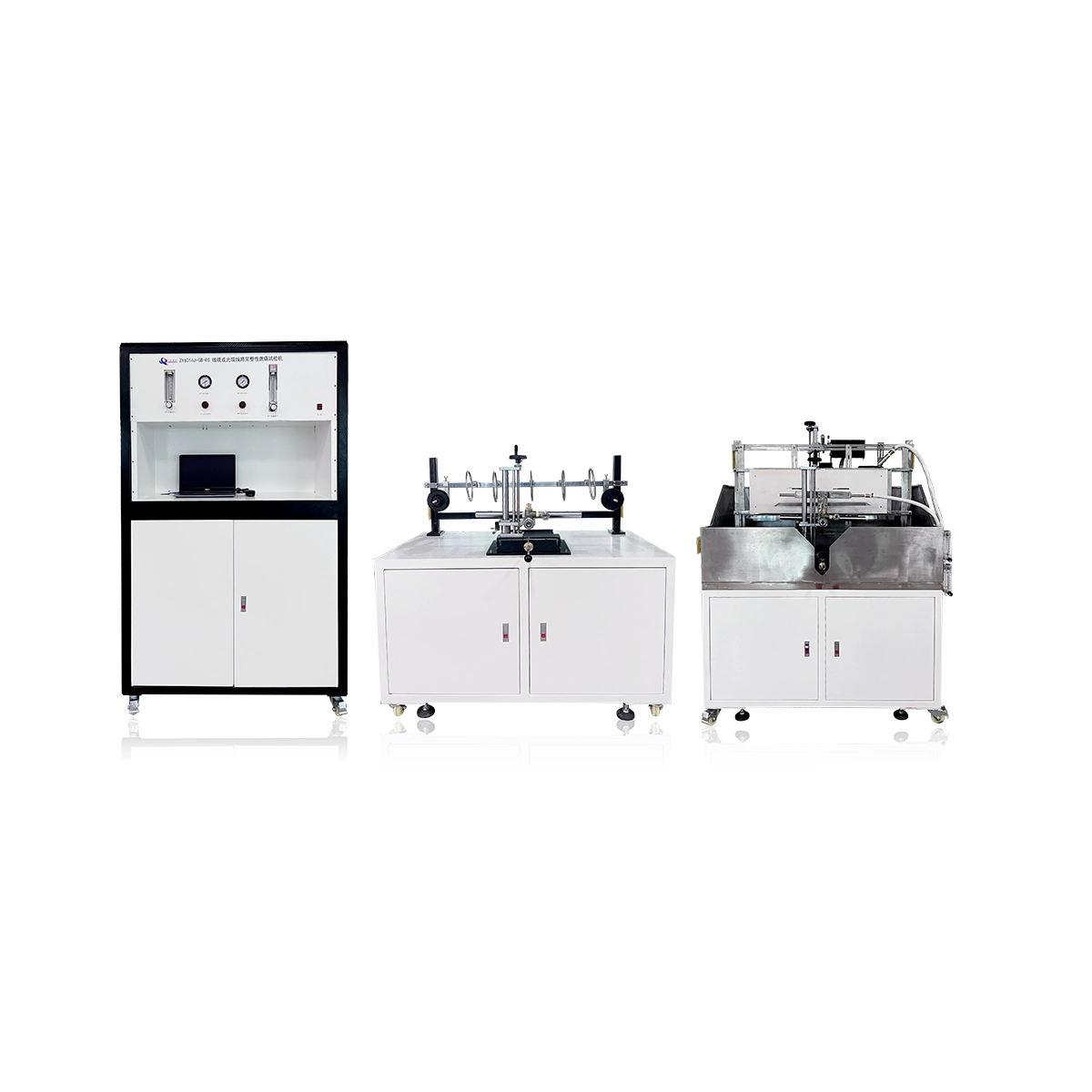
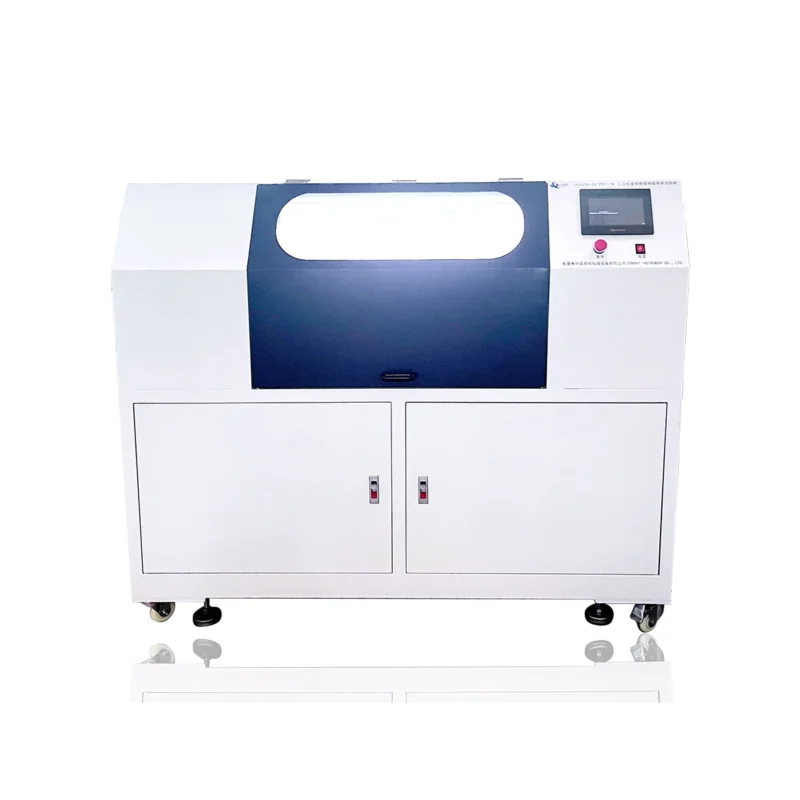
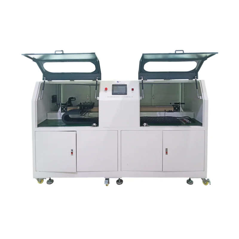
circuit integrity Apparatus
Brief Introduction
The Circuit Integrity Under Fire Conditions Apparatus simulates severe fire environments to guarantee that emergency and critical wiring systems stay operational when it matters most.
Highlights / Outstanding Features / Characteristics
- Real-Time Performance Tracking: Continuously monitors conductor continuity and circuit functionality while under direct flame exposure.
- High-Temperature Simulation: Subjects cable assemblies to intense, standardized fire conditions to measure insulation breakdown.
- Essential Safety Data: Delivers precise metrics on the exact fire-resistance thresholds of your electrical components.
- Compliance Verification: Helps manufacturers prove their cables meet strict regulatory and emergency survival standards.
Description
In compliance with:
- IEC 60331-11:1999 – Tests for electric cables under fire conditions – Circuit integrity – Part 11: Apparatus – Fire alone at a flame temperature of at least 750°C.
- IEC 60331-12:2002 – Tests for electric cables under fire conditions – Circuit integrity – Part 12: Apparatus – Fire with shock at a temperature of at least 830°C.
- IEC 60331-21:1999 – Tests for electric cables under fire conditions – Circuit integrity – Part 21: Procedures and requirements – Cables of rated voltages up to and including 0.61/1.0 kV.
- IEC 60331-23:1999 – Tests for electric cables under fire conditions – Circuit integrity – Part 23: Procedures and requirements – Electric data cables.
- IEC 60331-25:1999 – Tests for electric cables under fire conditions – Circuit integrity – Part 25: Procedures and requirements – Optical fiber cables.
- IEC 60331-31:2002 – Tests for electric cables under fire conditions – Circuit integrity – Part 31: Procedures and requirements for fire with shock – Cables of rated voltages up to and including 0.61/1.0 kV.
Main parameters
| Parameter | Specification |
|---|---|
| Supporting Gas | Compressed air (air pressure >10MPa) |
| Flowmeter | Two rotor flowmeters, adjustable air flow (0 to 200L/min) and gas flow (0 to 20L/min) |
| Thermocouple Installation | Torch positioned 45mm (±x mm) horizontally and 70mm (±y mm) vertically from the thermocouple center |
| Verification Judgment | Average thermocouple reading within (750±50)°C over 10 minutes, max difference ≤40°C |
| Ignition Device | Chengming small flame ignition |
| Fire Time | 0 to 99 minutes |
| Power Requirements | AC380V (±10%) / 50Hz |
| Operating Power | 1KW |
| Continuity Checking | In compliance with GB/T 19216.21, GB/T 19216.23, and GB/T 19216.31 |
| Heat Source Verification | Uses K-type thermocouples (φ1.5mm mineral insulated stainless steel sheath) |
| Test Wall | Non-combustible, non-metallic material (heat-resistant plate, 900mm height, 300mm width, 9mm thickness) |
| Torch Positioning | Horizontal: 100mm to 120mm from thermocouple, Vertical: 40mm to 60mm downward |