Product Details
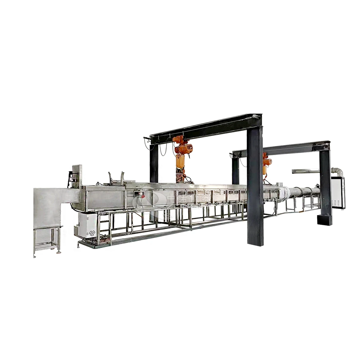
Steiner Horizontal Tunnel Furnace
Brief Introduction
The ZONSKY UL 910 Steiner Horizontal Tunnel Furnace is a premium fire safety testing system used to measure flame propagation and smoke density for construction and cabling materials.
Highlights / Outstanding Features / Characteristics
- Plenum & Duct Compliance: The standard method for testing CMP (Communications Plenum) fire wires, optical cables, and air ducts used in US and Canadian ventilation systems.
- Rigorous Test Environment: Subjects horizontally mounted samples to an 86 kW gas Bunsen burner for a strict 20-minute duration.
- Clear Pass/Fail Metrics:
- Flame Spread: Must not extend past 5 feet (1525 mm).
- Peak Smoke Density: ≤ 0.5 optical density.
- Average Smoke Density: ≤ 0.15 optical density.
- Crucial Safety Data: Delivers precise measurements for flame spread rate, smoke density, and heat release to ensure strict regulatory compliance.
Apparatus Details
In compliance with:
- UL 910 – “Test Method for Fire and Smoke Characteristics of Electrical and Optical-Fiber Cables Used in Air Handling Spaces transporting environmental air”
- NFPA 262 – “Standard Method of Test for Flame Travel and Smoke of Wires and Cables for Use in Air-Handling Spaces”
Main performance parameters
| Component | Specification |
|---|---|
| 1. Intake Chamber | |
| 1.1 Structure | Made of L-shaped stainless steel plate and components |
| 1.2 Air Inlet | 298.5 mm × 464 mm rectangular opening |
| 2. Combustion Chamber | |
| 2.1 Length | 7.62 m |
| 2.2 Structure | Constructed with 230 × 115 × 65 mm refractory bricks; one side is 230 mm vertical to the wall, and the other is 115 mm parallel |
| 3. Observation Window | |
| 3.1 Placement | Positioned at the front of the combustion chamber |
| 3.2 Installation | Placed 152 mm from the combustion chamber mouth, allowing full test sample visibility |
| 4. Burner | |
| 4.1 Type | Dual-port elbow combustion nozzle |
| 4.2 Nozzle Diameter | 19 mm |
| 4.3 Nozzle Distance to Center | 102 mm |
| 4.4 Nozzle Opening to Cover Plate | 191 mm |
| 4.5 Test Sample Size | 5.1 mm, ensuring full flame engulfment |
| 5. Trapezoidal Bridge for Cable Sample Installation | |
| 5.1 Usage | Supports a single bundled cable or cable in a trough (bus duct) |
| 6. Exhaust Transition Section | |
| 6.1 Composition | Includes exhaust section and variable diameter section |
| 7. Exhaust Duct | |
| 7.1 Length | 5.0 m (from the inner diameter of the 406 mm circular section to the smoke density measurement centerline) |
| 8. Measurement Section | |
| 8.1 Wind Speed Measurement | Two-way probe and differential pressure gauge measure wind speed at 500 mm from the smoke density centerline (range: 0.25–100 Pa) |
| 9. Smoke Density Measurement | |
| 9.1 Installation Position | 5.0 m in front of the straight circular pipe exhaust end |
| 10. Exhaust Duct Valve | |
| 10.1 Installation | Electric exhaust valve installed 1.68 ± 0.15 m downstream of the smoke measurement system |
| 10.2 Control System | Closed-loop feedback system controls air pressure in the combustion chamber air inlet |
| 11. Exhaust Fan | |
| 11.1 Power | AC 380V, 50Hz, 3 kW |
| 12. Temperature Measurement in Combustion Chamber | |
| 12.1 Floor Temperature Test | Uses a nickel-chromium (K-type) thermocouple with a 1.0 mm wire diameter, 9.5 mm outer sleeve, and 30 mm protruding hot end |
| 13. Analytical Instruments | |
| 13.1 Oxygen Measurement | Paramagnetic measurement (SIEMENS, Germany), accurately tracking oxygen percentage changes for combustion heat release analysis |